


Ex e Terminal Box Practicalities
One of the EEHA areas in which we have noted a tendency towards what we’ll refer to as “over-compliance,” in recent times, is in the verification that power dissipation inside Ex e terminal boxes is within allowable limits. Don’t get us wrong, we’re all about compliance and documentation, but some of the lengths we’ve seen people go to in this area are really not necessary, and in some cases the compliance exercise appears to indicate “problems” with installations that are in fact completely compliant, and more importantly, safe. Most of the issues we’ve encountered have to do with either:
-
- Unnecessarily restrictive specifications regarding the permitted maximum length of conductor inside an enclosure; or
- Overly conservative allowances for current in the conductors and terminals.
The simple fact is that in many cases Ex e boxes are used for marshalling of instrumentation and control signals, which have very low currents and hence very low heat dissipation. The requirements around conductor length and bunching/looming of more than six conductors are simply not relevant for these low-current applications. In this article we’ll explore the issues and give our take on what is reasonable in order to demonstrate a safe and compliant installation.
Firstly a quick re-cap on the basic principles in play – an increased safety enclosure, like all hazardous area equipment, has a Temperature Class, or T-rating, which describes its maximum surface temperature (including internal surfaces). Ex e terminal boxes are usually rated T6, or worst case T5 – maximum 100 oC. In the case of a terminal box, maintaining the T-rating requires that the Maximum Dissipated Power or MDP (heat dissipated inside the enclosure) is not exceeded. If the MDP is exceeded the additional heat may cause the surface temperature to exceed the certified T-rating and become an ignition risk (unlikely in most cases as there are very few T5 or T6 classified areas), or cause degradation to the insulating materials or enclosure itself, which may over time increase the likelihood of a failure/fault and a spark (more plausible). The power dissipation within a terminal box is simply the I2 R losses from the conductors and terminals – there is no other power dissipating equipment within a junction box.
The power loss per terminal is governed by:
P = I2 R
where R is made up of the resistance of the cable and the resistance of the terminal itself, so is more accurately written as:
P = I2 (Rt + Rc)
The cable resistance is dependent on the length of the cable, which strictly speaking, we don’t know until the installation is complete, but for the purposes of the calculation we usually make the assumption that the average length of the conductors for each terminal in the enclosure will be approximately equal to the length of the longest diagonal in the enclosure – L. This is the length of conductor that is connected to each terminal during the heat-rise test required by the Ex e equipment standard, so if we do our calculation the same way, we will be consistent with the type test carried out during the equipment certification process. So our power dissipation per terminal now becomes:
P = I2 (Rt + (ρc x L))
where ρc is the resistance per unit length of the conductor. To calculate the total power dissipation within an enclosure we simply calculate the power per terminal and add them up. We then check that the total power dissipated is less than the rated MDP of the box.
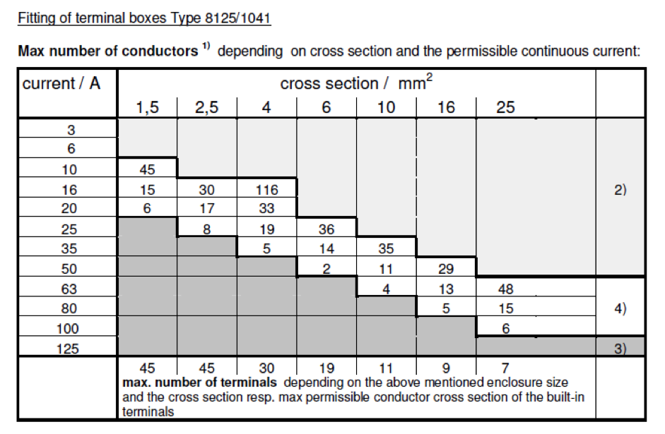
That’s all pretty straightforward, so what’s the trouble? The root-cause of the problems we’ve seen is in our view, an overly cautious interpretation of AS/NZS/IEC 60079.14 clause 11.2.4. The clause basically requires that we ensure the MDP of an enclosure is not exceeded, which we can do by referring to the box manufacturer’s documentation regarding the maximum number of terminals for a given conductor size and current (for manufacturers like Stahl who provide a table such as the one below setting out the information), or by referring to the MDP in Watts –provided on the terminal box label (manufacturers such as Abtech and CSE use this approach) and doing a calculation as outlined above to show that the combination of conductors and terminals within the box will not dissipate any more heat than is permitted.
The troubles creep in courtesy of two notes at the end of the clause, which we’ll reproduce below for convenience (emphasis is ours):
NOTE 1 The length of the conductors inside the enclosure should not exceed the diagonal length of the enclosure as this is the basis of calculations and type tests. Additional lengths of the conductors inside the enclosure running at maximum permitted current may give rise to increased internal temperature that may exceed the temperature class.
NOTE 2 Bunching of more than 6 conductors may also give rise to high temperatures that may exceed T6 and/or damage to the insulation and should be avoided.
The intent of Note 1 is to align the installation with the equipment type test, to make sure that the installation doesn’t produce more heat overall than the box was tested with during the certification process. Note 2 is intended to avoid local hot spots in cable looms.
The issue is that the length of conductor refers to the total length, so the 2 wires into and out of a terminal are each limited to half of the diagonal length of the enclosure. This is not practically achievable in many cases – terminals at the top of the box will require more than L/2 conductor length to reach them, but those at the bottom will require less, so if all the conductors are kept as short as possible – just reaching each terminal, on average the conductor length will be as per the type test (IEC 60079.14 Ed 5.0 has revised wording for this clause that clarifies that this is the intent). However, in the majority of cases installers are trained to leave conductors long enough to reach any terminal in the box so they can be re-terminated if needed (particularly in instrument and control installations), which means that often the total length of conductor per terminal will be longer than L in the final installation. So, does it matter?
To answer the question, consider the intent of the clause – to limit heat. Increased conductor length increases the resistance inside the box, which will increase the heat according to our equation
P = I2 (Rt + (ρc x L))
But the dominant factor in the calculation is the current – if the current is low the effect of the additional resistance is insignificant. And a great many of the Ex e terminal boxes in a plant will be devoted to instrumentation and control signals, where currents are tiny (typically a few hundred milliamps at most), so heating is negligible regardless of resistance. In these cases additional conductor is perfectly acceptable – there is no safety risk. The conductor-bunching issue raised by Note 2 to the clause is similarly irrelevant in these cases. Both of these notes are phrased as “should” rather than “shall,” indicating they are not mandatory (there is flexibility), and Note 1 includes a reference to conductors “running at maximum permitted current,” further indicating that instrumentation and control boxes should not be cause for concern.
Take the example of 1.5 mm conductors, carrying the hold-in current for a relay – say 200 mA (which would be at the upper end of the load in the majority of control circuits) connected through 2.5 mm2 terminals in an Ex e box. We use the actual load current (or a conservative estimate) for the calculation, to align with the heat-rise type test, which is based on continuous current. It’s not necessary to consider faults, because they are not continuous – the circuit protection will typically disconnect before significant heating can occur. Even if we allow a whopping 2 m of conductor per terminal inside the box, the power dissipation per terminal (using AS/NZS 3008 for cable resistance at 75 oC, and Weidmuller terminal resistance data) is tiny:
P = 0.2 A2 (0.36 mΩ + (0.0165 Ω/m x 2 m)) = 1.33 mW
This equates to about 750 terminals per watt of power dissipation, so a box with an MDP of 2 W (at the lower end of typical values – a small enclosure) would be able to accommodate 1500 terminals, each with 2 m of conductor connected. We would run out of space long before we hit the power limit! In the table for the Stahl enclosure above, this equates to the grey region labelled (2) – to paraphrase– “at these low currents you may have as many terminals as you can fit in the box, space is the limiting factor, not heat.” In such cases we would argue cable length is not important, and if you are doing a calculation to document that everything is fine , there’s nothing to stop you from calculating using a longer length than the enclosure diagonal – 2L or even longer if needed to better reflect the actual installation. In the case of manufacturers like Stahl, where a table is used, a calculation is not as simple, but the same basic premise applies – at low currents additional length of conductor is not an issue, because you will run out of space in the box long before you hit the heat limit. (We might explore this a bit further in a future post if there is any interest.)
Of course, in applications where the current is not negligible (e.g. light and power distribution) there may be a genuine risk to safety and we must take the proper care. Certainly a calculation or verification against manufacturer’s table must be completed to show the heat dissipation is OK, but we suggest that the current used in the calculation should be the actual load current, or for a more conservative result, the circuit protective device rating. Using the terminal or cable rating may give unduly conservative results and create the impression of a problem where there is none. And again, there’s nothing to stop you from calculating using a longer conductor length than L if the field installation is likely to need more conductor. It’s worth noting that in lighting and power distribution boxes the conductors may be larger and therefore have correspondingly larger bending radii, so there is less inclination towards leaving spare conductor in the box – it’s not physically possible, so problems with excessive cable length and bunching of conductors are less likely to be encountered with high current installations.
Overall, we suggest a common-sense approach with verification of Ex e terminal boxes. Keeping in mind the overall aim of limiting I2 R losses inside the enclosure allows us to identify high and low risk situations. In particular we offer the following guidelines:
- Additional cable lengths inside instrumentation and control terminal boxes where all circuit current are low will not cause significant heating. Bunching of cables is likely to be acceptable for these applications.
- Higher currents require more caution, but conductor lengths in such applications are often self-limiting due to the physical properties of the installation.
- Calculations or verifications against manufacturer data should be performed using the load current, rather than the cable or terminal rating, which may give overly conservative results.
Hopefully the above is of some assistance in developing your EEHA compliance documentation. Please feel free to contact us if you have any questions, or would like to throw your 2c into the debate.